10+ dac block diagram
I A resistive nw digital controlled electronic switches a voltage ref and I to V. 35RN1012 Diagram Reference.

Tda1543 Dac Datasheet Pinout Circuit Video Faq
The DAC features a 10-bit resolution and has one continuous time output with high-drive capabilities.
. The basic building blocks of a DAC are-. DAC Block Diagram Current Output mode p30 DAC Equations Parameter Definitions Current mode p31 DAC Block Diagram Voltage Output mode p32 DAC Equations. 12 Spline Coupler Link for HOWSE 10 Rotary Cutter Howse Part.
Ad Templates Tools To Make Block Diagrams. To save a brief description of a subblock diagram click Block Diagram Parameters on the toolbar. Number of steps 2n.
A simple block diagram consists of a data source and a display instrument. Where n is the number of bits. Written 36 years ago by teamques10 33k.
Therefore there are 2 steps in 1-bit resolution. The block diagram of DAC is shown in the. Functional Block Diagram 3 Description The DAC5652A is a monolithic dual-channel 10-bit high-speed digital-to-analog converter DAC with on-chip voltage reference.
The block diagram is updated with clarifications to the output signal routing. The DAC conversion can be started from the application by writing to the Data. A Digital to Analog Converter DAC converts a digital input signal into an analog output signal.
TONGUE JACK TJP2001B Howse Part. Cascade several low resolution stages to obtain high overall resolution. The digital signal is represented with a binary code which is a combination of bits 0 and 1.
Functional block diagram power-on reset dac register input control logic sync clr r_sel dgnd v logic v dd agnd sclk sdi sdo v out v fb ldac alarm power-down control logic precision reference. This is a major drawback which is eliminated in modern DAC to make them work from a single power source. Pin digram block diagram of.
-10 0 10 a without calibration Code SB RNG0 RNG1 0 1000 2000 3000 4000-10 0 10 b. Clarifications of the block diagram and the DAC Output sub-section of the DAC peripheral has been made. This figure shows the conversion of analog to digital in 2-bit.
Functional Software Electrical etc. If you want to use an inbuilt NI measurement board as the data source click NI-DAQmx Driver in the. DIAdem saves block diagrams with the filename extension dac.

Successive Approximation Adc Wikiwand

Tda1543 Dac Datasheet Pinout Circuit Video Faq

One Channel 0 10v Dac I2c Digital To Analog Converter Store Ncd Io

Successive Approximation Adc Wikiwand

Digital To Analog Converter Dac Types Working Applications Electronic Engineering Analog To Digital Converter Electrical Wiring Colours
Are There Any Headphones With A Built In Equalizer Quora

Adas1000 1 Datasheet And Product Info Analog Devices

Omni Design Technologies Omni Design Technologies

Digital To Analog Converter Wikiwand

What Is A D Converter How To Wire It
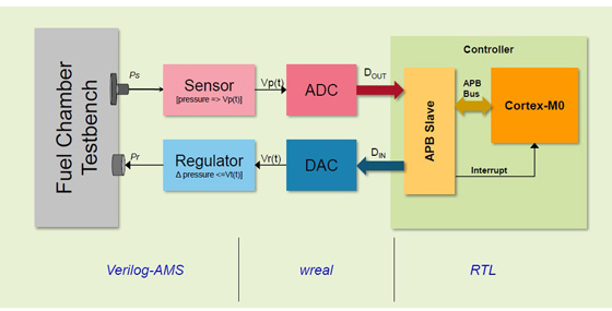
Arm Based Microcontrollers Using Cadence S Mixed Signal Solution Mixed Signal Design Cadence Blogs Cadence Community
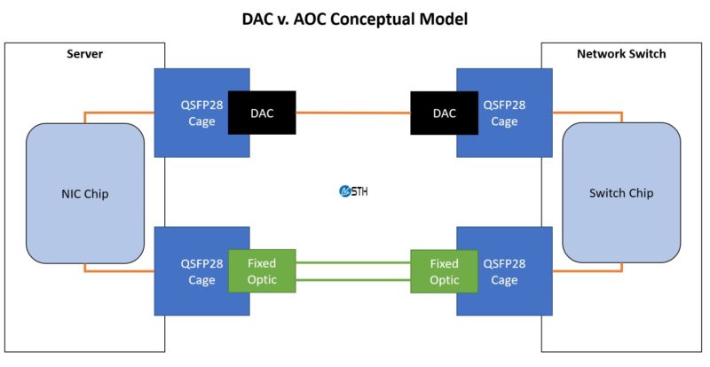
What Is A Active Optical Cable Aoc

One Channel 0 10v Dac I2c Digital To Analog Converter Store Ncd Io

Awr2944 Data Sheet Product Information And Support Ti Com

Block Diagram Of The Receiver Section All High Speed Signal Download Scientific Diagram

Ti Digital Radio Block Diagram Digital Radio Digital Radio

Rgb Video Out Block Diagram Video Logic